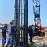
Types of bored pile drilling machines
I. Circulating bored pile drilling machine.
1. Structure:
From the bottom of the bored pile borehole, the parts are assembled together in the following order: Bored pile drill bit, hammer, sections that need to be drilled have a scarf-shaped cross-section, sections that need to be drilled on bored piles have an aperture-shaped cross-section. (1 piece), universal joint, flexible pipe for bentonite solution, pump (or suction machine).
The universal joint has a hook attached to the hook of the cable hoist for lifting and lowering when necessary. The upper flange of the universal joint is fixed to the flexible pipe, the lower flange of the universal joint rotates with the section that needs to have a rectangular cross section. password.
The boom section has a longer cross-section than the boom sections with a scarf cross-section to make it easier to install additional boom sections when gradually increasing the depth.
The section needs to have an aperture-shaped cross-section that slides into a rotary wheel with a corresponding square hole. When the rotary wheel is driven to rotate, it transmits torque to the section that needs to have an aperture cross-section and causes the parts installed under this section (including sections that need to be drilled with a ring cross-section, the mace and the drill bit) to rotate.
There are two types of bored pile drilling bits of this machine: soil drilling and rock drilling. The soil drill bit has rows of cutting teeth to cut the soil. The rock drill has many small balls with a rotating axis on the drill bit, each of which has many small teeth made of impact-resistant and wear-resistant steel. When the bored pile drill bit rotates, these small teeth grind and break the rock at the bottom of the bored pile drill hole.
The mace has the effect of creating pressure on the bored pile drill bit.
2. Method of breaking rock into chips (drilling mud):
Soil drills use the cutting force of teeth. Rock drilling uses force to break, grind and impact when the drill bit rotates.
3. How to remove chips from drill holes:
Forward circulation drilling:
The pump sucks solution from the tank and pumps it into the drill hole in the following direction: Pump –> Flexible pipe –> Universal joint –> Sections to be drilled –> Through the mace –> Through the drill bit. The fluid flow erodes the bottom of the borehole and then guides the chips up along the scarf space between the drill rod and the borehole wall. After the fluid flow exits the borehole, it is guided into the chip settling tank, then flows through the chip storage tank. From the reservoir, the solution is again pumped by the pump to the bottom of the borehole.
A solution with a high density will lead to chips more easily than a solution with a low density.
In case the borehole diameter is large, the fluid flow velocity from the bottom of the borehole to the mouth of the borehole is very slow, and the drill chips tend to sink back to the bottom of the borehole. So the drilling speed will be slow.
Reverse circulation drilling:
Forward circulation drilling has the disadvantages as mentioned above. In case of large diameter, reverse circulation drilling is often used.
The vacuum cleaner sucks up chips from the bottom of the drill hole. The chips are sucked up with the solution in the following direction: Drill bit –> Mace –> Sections to be drilled –>
Universal joint –> Flexible pipe –> Through suction machine –> Discharge into chip settling tank. From the settling tank, the solution flows back into the borehole.
Thus, the drilling chips pass through the suction machine. The pump impellers of the vacuum cleaner have a special structure to guide chips through. For the same circulating drilling machine, the chip vacuum's capacity is 2 to 3 times greater than the capacity of the fluid pump.
4. How to gradually increase drilling depth:
As the drill chip is guided up, the parts gradually slide down, the rod section with a flange section also slides down until the upper flange of this rod section is about to touch the rotary wheel, then an additional section of the drill rod with a rim section must be installed. towel to continue drilling deeper.
In terms of structure, the flanges of the sections that need to be drilled are fitted together with bolted joints, transmitting torque through arbor, and these joints have rubber seals to prevent drilling fluid leakage.
The rotary wheel has 4 center compensators (2 large center compensators, 2 small center compensators). When these 4 center compensators are installed on the rotary wheel, they form a square hole that fits tightly, requiring a cross-section to transmit torque. from the center, a wide hole is created between the rotary wheel and the flange can be pulled from under the rotary wheel (under the machine base) to the top of the rotary wheel (on the machine base).
The steps are as follows:
Step 1: Remove the 4 center compensators from the rotary wheel, creating a wide hole in the middle of the rotary wheel.
Step 2: Use the universal joint hoist to lift the drill rod and the parts installed below until the upper flange (flange A) of the rod section with the top scarf cross-section is on the rotating tray.
B3. Reinstall the 2 large center compensators to make the hole in the middle of the rotary wheel smaller, use a shim to hold flange A on the rotary wheel. (The additional mounting space is now on the turntable).
B4. Remove the joint at flange A, the section with the flange section is removed from the section with the scarf section.
B5. Install the new boom section on top of flange A. The top flange of this newly installed section is flange B.
B6. Again, remove the 2 large center compensators to drop the newly installed rod section, install the 2 large center compensators again, then use a shim to hold flange B on the rotary tray.
B7. Reinstall the section that needs the flange section to flange B.
B8. Remove the 2 large center compensators to drop flange B below the turntable.
B9. Reinstall the 4 center compensators.
Disassembly and assembly of the sections must ensure that the solution does not leak through the joints and is quite time-consuming, so the rock drill bit can be installed from the beginning without using a soil drill bit.
Currently popular circulatory drills include GPS 15, GPS 22 from China, YP-3AM-500 installed on the base machine of Russian Maz car...
II. Pile drilling machine, twisting chicken intestines!
– Create pile holes using spiral drilling equipment and spiral reel system (creating bored piles, Diaphragm walls)
– Create pile holes using drilling equipment (creating bored piles)
– Create pile holes using round bucket digging equipment (create round pile piles)
– Create holes with hydraulic flat bucket digging equipment (create Barrette piles, diaphragm walls[1] Diaphragm walls)
– Create holes with a counter-circulating pump-type bored pile drilling machine
– Create holes using the anti-circulation pumping water pump method
– Create stake holes by digging manually
* The following development steps can be mentioned here:
- Pile ; is a pile whose hole is constructed using different drilling methods such as bucket drilling, backwash drilling, etc.
– Bottom-extended bored pile: is a bored pile with the bottom diameter of the pile expanded larger than the diameter of the pile body. The load carrying capacity of this pile will increase to about 5- 10% due to the increased load carrying capacity under the tip
– Barrette pile: is a bored pile but has a non-circular cross-section with different cross-sections such as rectangular, cross, I-shaped, H-shaped... and holes are created with a grab bucket. The load carrying capacity of this pile can be increased up to 30% due to increased lateral load carrying capacity.
– Bored piles with bottom cleaning and cement grouting (CNRBD): are bored piles that apply bottom cleaning technology (by high pressure scouring) and bottom reinforced cement grouting (along with high pressure). This is the most recent development in bored pile construction technology to dramatically increase the load-carrying capacity of bored piles (up to 200 - 300%), allowing maximum use of the durability of piled concrete.

Contact Info:
Contact Info:
- Address: No. 12, Street 27, Van Phuc Urban Area, Hiep Binh Phuoc Ward, Thu Duc City, HCMC
- Phone number: 0915.611.337 Mr. Phuong Or 0915.411.337 Mr. Quan
- Email: [email protected] or [email protected]
- Website: Lethycorp.com
- Road Map: See


