1.PURPOSE OF THE PROVINCE TESTING
Static compression test is conducted before construction Pile Mass-based assessment aims to determine the bearing capacity of piles, and data on strength, deformation, and load-displacement relationships of piles serve as a basis for designing or adjusting design projects, and selecting appropriate equipment and construction technologies.
2.PRINCIPLES OF US EXPERIMENT
The test is carried out by using a static load to press the pile axis so that under the action of the pressure, the pile sinks deeper into the ground. Loading on the pile head is carried out by hydraulic jacks with the reaction system being the loading platform, anchoring or a combination of both. The data on load, displacement, deformation, ... obtained during the experiment is the basis for analysis and assessment of the load capacity and the load-displacement relationship of the pile in the ground.
3.NUMBER OF TEST STEELS
Due to design regulations, it is normally taken to be equal to 1% the total number of piles of the building but in all cases not less than 02 piles.
4.EXPERIMENTAL EQUIPMENT US
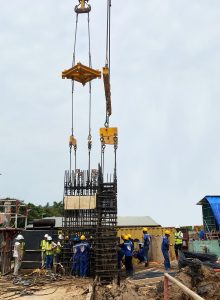
Experimental equipment includes:

Decorative: Used in the static compression test of piles at the construction site are precast concrete counterweights arranged in blocks on a steel supporting beam system.
Maximum total load : 120% Maximum test load
Support beam system: The system consists of a reinforced steel frame, calculated and manufactured to withstand the maximum test load Pmax = 300 tons. The main load-bearing beam is a 400 mm high steel box girder with box reinforcement. The secondary girder system is a 500 mm high steel girder supported on a support system. This girder system is reinforced to withstand the load and does not deform under load or throughout the testing process.
Support system: Is a system consisting of many precast reinforced concrete loads of different sizes and loads (tonThe different support structures are sufficient to support the experimental counterweight system placed on the ground, which serves to support the loaded beam system. The support system is calculated with sufficient cross-sectional area to ensure that there is no settlement when the load is applied for the experiment, and that it does not affect the operation of the piles or other equipment throughout the experiment.
Load system: Is a system consisting of many precast reinforced concrete loads of different sizes and loads (tonFor different pile types, the test counterweight is placed on a secondary beam system to ensure balance. The counterweight load is calculated according to the requirements for each pile type and the required design load.
Loading system:The load testing system in the construction project uses hydraulic jacks with a lifting capacity greater than or equal to ≥ 150% of the maximum test load. The hydraulic jacks are inspected and certified by authorized units. This jack system is placed on top of the test pile, with the axis of the hydraulic jack coinciding with the axis of the test pile. The jack system and load transfer beam ensure that the load force is transmitted precisely to the center of the test pile. (see the appendix of the certificate of inspection of the hydraulic jack)
Force measuring system:Force measuring system using hydraulic meter with measuring load 0-600 kg/cm2. The compressive force acting on the test pile head is calculated through the readings of the pressure gauge and the lifting coefficient of the hydraulic jack, which is tested and certified by functional units. (see the appendix to the Certificate of Inspection of Pressure Gauges)
Hydraulic pump system: The hydraulic pump system is connected to the hydraulic jack by pipes that supply oil to the jack, allowing for adjustment of the jack's lifting capacity as desired. The pump flow rate is 3 liters/minute, and the maximum pressure is 600 kg/cm².2.
Displacement measuring system: Including 04 settlement gauges with a maximum measuring range of 50mm with an accuracy of 0.01mm, which are fastened to the test pile body through a magnetic support system and steel shackles, which are tested and issued by functional units. accreditation. (see the appendix of the Certificate of Inspection of the Timer 04 pieces)
Displacement meter mounting system: Is a support system with magnetic legs by permanent magnet, fastened to the steel shackle system mounted on the top of the test pile.
Standard beam system: standard girders, also known as metering bridges, have sufficient rigidity and are not affected by weather shocks (can be box girders, U, I, V beams), the distance from the foot of the bridge supports. clock, datum to the center of the test pile is not less than 3D
Standard landmark system: The standard landmark system used for the construction is a sectional steel system buried in the ground. The hardness of the reference bar ensures no deformation during the test and is not affected by external influences.
5.EXPERIMENT PREPARATION US
The piles being tested should be checked for quality according to current standards for pile construction and acceptance.
Static compression testing is conducted for piles that have had enough time to recover the structure of the soil damaged during construction or the concrete reaches strength. For prestressed reinforced concrete piles, rest time from completion of construction concrete pile pressing until the experiment is 07 day. For bored piles, the rest time from completion of construction to testing is 21 day.
The test pile head can be cut or added, but must meet the following requirements:
– The distance from the pile head to the main beam must be sufficient to install jacks and measuring equipment;
– The pile head is made flat and perpendicular to the pile axis; if necessary, additional reinforcement is required to prevent localized failure under test loads;
– Measures should be taken to eliminate friction in the pile section above the foundation base if it is considered to affect the test results.
The jack must be placed directly on the pile head pad, centered relative to the center of the pile. When using multiple jacks, jacks must be arranged so that the load is transmitted axially, centered on the pile head.
The pile head clamp is fastened to the pile body, approximately 0.5 diameter or width from the pile head.
The standard beams are placed parallel to both sides of the test pile, the beam supports are firmly buried in the ground. The displacement meter is mounted symmetrically on either side of the pile head and is stably mounted on the reference beams, the base of the displacement meter is supported on the pile head clamp or the pile head pad (or vice versa).
The installation distance of equipment is specified as follows:
– The distance from the center of the test pile to the center of the anchor pile or anchor wing is greater than 3D but in no case less than 2m;
– The distance from the test pile to the nearest point of the larger support bearings must be greater than 3D, but in no case less than 1.5m;
– The distance from the test pile to the standard beam supports shall not be less than 1.5 m;
– From the reference point to the test pile, anchors and supports of the truss are loaded with a distance greater than 5D, but in all cases not less than 2.5m.

6.EXPERIMENTAL PROCEDURES
Before conducting the test, the experimenter preloads to check the operation of the equipment and creates contact between the test pile head and the test device. Preload with 5% of design load, hold the load for 10 minutes then reduce the load to 0% level, adjust the displacement gauges to the load level 0%.
TABLE OF EXPERIMENTAL PROCEDURES US
|
Load level experiment |
Time to maintain test load to the top of the test pole |
Time to monitor and record experimental data |
|
5% |
Hold for 10', to eliminate deformation caused by loading. | |
|
0% |
Record the initial data. | |
|
25% |
Minimum is 1 hour and achieve the conventional stable settlement of 0.25 mm/hr, but not more than 2 hours. | Record the results at the time: 0; ten'; 20'; 30'; 45' and 60'. |
|
50% |
Minimum is 1 hour and achieve the conventional stable settlement of 0.25 mm/hr, but not more than 2 hours. | Record the results at the time: 0; ten'; 20'; 30'; 45' and 60'. |
|
75% |
Minimum is 1 hour and achieve the conventional stable settlement of 0.25 mm/hr, but not more than 2 hours. | Record the results at the time: 0; ten'; 20'; 30'; 45' and 60'. |
|
100% |
Maintain in 6 o'clock and reach the conventional stable settlement. | Record the results at the time: 0; 10',20'; 30'; 45', 60'; 120' and continue 60' at a time until the allotted time has elapsed. |
|
50% |
30 minutes |
Record the results at the time: 0 ; 10', 20' and 30'. |
|
0% |
60 minutes |
Record the results at the following times: 0; 10'; 20'; 30'; 45'; & 60'’ |
|
25% |
30 minutes |
Record the results at the time: 0, 10', 20' and 30'. |
|
50% |
30 minutes |
Record the results at the time: 0, 10', 20' and 30'. |
|
75% |
30 minutes |
Record the results at the time: 0, 10', 20' and 30'. |
|
100% |
30 minutes |
Record the results at the time: 0, 10', 20' and 30'. |
|
125% |
Minimum is 1 hour and achieve the conventional stable settlement of 0.25 mm/hr, but not more than 2 hours. | Record the results at the time: 0, 10', 20' and 30', 45' and 60'. |
|
150% |
Minimum is 1 hour and achieve the conventional stable settlement of 0.25 mm/hr, but not more than 2 hours. | Record the results at the time: 0, 10', 20' and 30', 45' and 60'. |
|
175% |
Minimum is 1 hour and achieve the conventional stable settlement of 0.25 mm/hr, but not more than 2 hours. | Record the results at the time: 0, 10', 20' and 30', 45' and 60'. |
|
200% |
Maintain in 24 hours and reach the conventional stable settlement, whichever is longer. | Record the results at the time: 0; 10';20'; 30'; 45', 60'; 120' and continue 60' at a time until the allotted time has elapsed. |
|
150% |
30 minutes |
Record the results at the time: 0, 10', 20' and 30'. |
|
100% |
30 minutes |
Record the results at the time: 0, 10', 20' and 30'. |
|
50% |
30 minutes |
Record the results at the time: 0, 10', 20' and 30'. |
|
0% |
1 hour |
Record the results at the following times: 0', 10', 20', 30', 45', 60'’ |
Regulation of increase and decrease of load
– Apply the load in increments up to the maximum expected test load of 200% Ptk, with each load increment equal to 25% of the design load. A new load increment should only be applied when the pile head settlement rate reaches conventional stability (ΔS ≤ 0.25mm), but not for more than 2 hours. Maintain the maximum load until the pile head settlement reaches conventional stability or for 24 hours, whichever is longer.
– After the loading is complete, if the pile is not damaged, proceed to reduce the load to 0. Each load reduction step is twice the load reduction step, and the holding time for each step is 30 minutes, except for the 0-ton load step which may be longer.
Regulations on sabotage, stopping and termination of experiments
- Regulations on destruction of piles
– At load levels lower than the maximum test load, pile head settlement increases continuously without increasing the load.
– The pile does not achieve the conventional stable settlement after 24 hours of holding any load.
– At any load, the total displacement exceeds the pile size of 10%. .
– The pile material has been damaged.
– The rate of pile settlement at each load level is five times greater than the previous load level (sudden increase in settlement).
- The experiment must be stopped if the following phenomena are detected:
– The benchmarks are incorrectly placed, unstable, or damaged.
– The trigger is not working.
– The propulsion system is unstable.
– The pile head is broken, and the compression beam is tilted.
– The ground has been damaged.
The experiment can be continued after the issue has been addressed or resolved.
- End of experiment
– Achieved the experimental objectives as outlined in the plan.
– The test piles were vandalized.
7. REPORT OF EXPERIMENTAL RESULTS US
Report the results of the pile static compression test carried out according to the standard TCVN 9393:2012, including:
– Explanation of the results report.
– Summary table of experimental results.
– Field experiment data sheet.
– Experimental results charts:
- Load-Displacement Relationship Diagram.
- Transposition-Time Relationship Diagram
- Load-Time-Displacement Relationship Diagram
- Load-Time Relationship Diagram
– Conclusion and recommendations.
8.TREATMENT AND STRENGTHENCE OF US TEST PILES
– The pile head may need to be trimmed or extended as appropriate; this work is handled by the testing contractor to suit the nature of the assigned testing work (this depends on the construction site and testing equipment).
– Apply Sika GP mortar to smooth the pile surface.
Test the system of experimental equipment, the lifting capacity of the hydraulic jack, the oil pump, the sensitivity and uniformity of the pressure gauge and the displacement gauge. Inspection period of measuring devices and tools.
9. SAFETY WORKS AND FIRE PREVENTION AT THE WORKS
In addition to complying with labor safety regulations in construction, it is necessary to observe the following regulations in the experiment:
– Unauthorized personnel are not permitted in the testing area.
– Inspect the safety of the load-bearing beam system, supports, and bearings.
– During the rainy season, the experimental unit must have a tarpaulin to protect it from the rain.
– Because static compression testing is conducted in the field and uses heavy equipment, appropriate safety measures are necessary to prevent workplace accidents and damage to testing equipment.
– During the experiment, no other equipment is permitted to operate near the experiment area to ensure the safety and accuracy of the data collected.
– After the experiment is completed, all experimental equipment must be dismantled, transported away from the site, and carefully maintained.
– To prevent fires, measures must always be taken to prevent sources of ignition and flammable environments, as well as specific regulations regarding the use, operation, and storage of machinery, equipment, materials, and products that could be sources of ignition. Flammable materials must be stored neatly and properly, and isolated from flammable environments.
PROFESSIONAL POWER CONSTRUCTION WORKS
CONSTRUCTION OF DRILLING Pile - Rock Drilling
Contact information:
- Address: No. 12, Street 27, Van Phuc Urban Area, Hiep Binh Phuoc Ward, Thu Duc City, HCMC
- Phone number: 0915.611.337 Mr. Phuong or 0915.411.337 Mr. Quan
- Email: [email protected] or [email protected]
- Website: Lethycorp.com
- Road Map: See