I. Technology requirements.
1. Concrete.
a) Request for distribution.
– Use ready-mix concrete with grades B20, B25, etc.
– Concrete pouring follows the principle of using long pipes (grouting), so the concrete mix ratio must also be suitable for this method (concrete with sufficient plasticity, cohesion, and flowability in the pipe). For the grouting method, bentonite solution helps stabilize the borehole walls; the concrete pump pipe is always kept submerged in concrete, and as the concrete gradually rises, it slowly pushes the bentonite solution out of the bored pile borehole.

– Method of pouring concrete for vertical bored piles using casing pipes: Used when the soil is weak, in areas with surface water or caves.
+ Temporary bulkhead pipe: retracted during the concreting of piles
+ Permanent wall pipe: Leave after construction
Advantages: Good pile quality
Cons: The wall pipe construction machine is bulky and noisy.

– Concrete:
+ Ratio N-XM 50%.
+ Weight of XM 400kg/m3 of concrete.
+ Sand about 45%.
– The optimal cone slump is 181.5 cm (usually 13-18 cm). Concrete supply must be continuous so that the entire time for concreting a pile is completed is 4 hours.
– Additives can be used to achieve the above properties of concrete.
– The largest diameter of the aggregate is the smallest of the following dimensions:
+ A quarter of the eyelet of the reinforced cage.
+ Half layer of reinforcement protection.
A quarter of the inner diameter of the concreting pipe.
– It is necessary to select a ready-mix concrete plant with modern technology, and the aggregates and water must be clean according to requirements. Trial mixing and testing of the plant's capacity and concrete quality are required. The concrete mix design and additives should be selected before mass pouring.
-At the construction site, each commercial concrete truck must be checked for the preliminary quality, the time to start mixing and the time when the concrete is finished, the cone slump. Each pile must take 3 combinations of samples to test the strength. Must have strength test results from a fully legal and independent laboratory.
b) Equipment used for concrete work.
– Ready-mix concrete is delivered in specialized vehicles.
– The concrete is poured from the hopper to the required depth.
– A hopper collects the concrete from the truck and connects to a pipe.
– Pipe and funnel holders.
2. Reinforcing steel.
– The reinforcing steel used must be of the correct type and specifications as stipulated in the approved design; the reinforcing steel must have sufficient manufacturer's certificates and test results from an independent, legally qualified laboratory for each batch before being put into use…
– The steel reinforcement, after being fabricated and assembled into a cage, is transported and placed on a rack near the installation site to facilitate subsequent construction.
– The length of the tie joint is 45d (d - diameter of the steel pile), the tying steel has a diameter of 3.2 (mm).
– The stirrup ties are made using single-sided electric welding, with a weld length of 15d. The reinforcing stirrup is welded to the high-strength steel.
– The edge-to-edge distance between the main reinforcement bars must be greater than 3 times the diameter of the coarse aggregate particles in the concrete.
– The reinforcing clamp should be placed at the outer edge of the main reinforcement bar. The main reinforcement bar should not have hooks, and the hooks, made according to construction technology requirements, should not protrude inside, affecting the operation of the concrete pipe.
– The inner diameter of the steel cage must be more than 100mm larger than the outer diameter at the concrete pipe connection point.
– To ensure the thickness of the concrete cover, positioning markers must be placed on the main reinforcement bars for each cross-section along the pile depth.
– According to TCXD 206 – 1998, the permissible error for manufacturing steel reinforcement cages is:
3. Bentonite solution.
– In bored pile construction, the use of bentonite slurry has a significant impact on pile quality:
+ The level of the solution is low, the supply is not enough, the bentonite is diluted, the water is easily separated, leading to the collapse of the borehole wall, the breakage of the concrete pile.
+ The solution is too dense, the sand content is high, leading to difficulty in pouring concrete, blocking the pouring pipe, large amount of sand deposited at the tip of the pile will reduce the load capacity of the pile.
– The effects of bentonite solution.
+ Make the pit wall not collapse thanks to the solution that penetrates deep into the sand crevices, cracks, and mixes with loose sand to keep the sand and debris from falling and forming an elastic film around it. The wall of the pit keeps water from seeping into the wall.
+ Create a heavy environment to lift up the soil, rock, drilling debris, sand to the top to overflow or suck out of the borehole.
+ Slow down the sedimentation of sand particles, in the state of small particles in suspension to easily handle sediment.
-With the use of bentonite clay mortar, the borehole wall is stabilized by the following two factors:
+ Bentonite solution acts on the borehole wall a value of hydrostatic pressure that increases with depth.
+ The stalactite particles will adhere to the borehole wall and penetrate into the holes on the hole wall to form a thin, waterproof and durable film.
Therefore, having a sufficient supply of high-quality bentonite solution is crucial for the construction process and the quality of bored piles.

b) Procedure for mixing Bentonite solution.
– Pour the calculated amount of water into the mixing tank.
– Pour the bentonite powder slowly according to the design.
– Pour in the additive slowly, if any.
– Continue mixing for 15-20 minutes.
– Pour in the remaining water and mix for 10 minutes.
– Transfer the mixed bentonite solution to a storage tank, ready for supply to the borehole, or mix it with the recovered bentonite solution that has been filtered through a sand sieve for supply to the borehole.
The drilling fluid mixing station at the construction site includes:
A bentonite mixer.
+ Some manufacturing equipment ensures the dissolution of Bentonite powder in water
+ One or more storage tanks or silos allowing the site to prepare sufficient reserves to prevent any drilling problems.
+ Some sanitary equipment ensures the separation of large residues by sieve and sand by centrifugal cyclone.
c) Some notes when using Bentonite to construct bored piles.
– Mixing ratio: 30-50 kg Bentonite/m³, depending on water quality.
– Water used: clean water, tap water.
– Additives to adjust pH: NaHCO3 or similar.
Depending on the specific case, to achieve the standards set forth in the regulations, some additives such as Na2CO3 or NaF may be used.
– During construction, the surface of the fluid in the pile hole must be at least 1.0m above the groundwater level. When affected by fluctuations in groundwater levels, the fluid surface must be at least 1.5m above the groundwater level.
– Before pouring concrete, the density of the solution in the area from 500mm from the bottom of the hole must be less than 1.25; sand content 8%; viscosity 28s to easily push it to the surface.
– The density and viscosity selected must be suitable for the geotechnical conditions and the method of solution application.
– In addition to bentonite solution, CMC, synthetic solutions, salt water solutions, etc., can be used depending on the geological conditions of the construction site.

II. Technological process for construction of bored piles by twisting bucket method in bentonite solution using wall pipes.
The technological process of bored pile construction is shown in the order of work according to the diagram:
1.This is an important job that affects the position and distance of the columns of the work, is the job of locating the location of the work from the design drawings to the field.
– Based on the site plan issued by the chief architect's office or equivalent agency, establish the project boundaries. These boundaries must be inspected and approved by the competent authority.
– From the pile foundation site plan, establish a positioning system and control grid for the structure using the X,Y coordinate system. These grids are transferred and fixed to adjacent structures or combined to form positioning markers. These markers are carefully fenced and protected, and continuously inspected to prevent displacement due to collisions and subsidence.
– The borehole and pile centerline are positioned before the casing is installed, and two inspection markers are kept perpendicular to each other and at equal distances from the pile centerline.
2. Lower the wall pipe.
– The casing pipe (or casing) made of steel with a large diameter of approximately 100-150mm for the drill bucket, we choose 900mm long (2.5-3)d, take 2m, place it at the top of the borehole, protruding about 0.6m above the ground.
– The casing pipe has the following functions:
+ Positioning and guiding the drill to follow.
+ Keep the surface of the borehole stable to ensure that the wall does not collapse on the borehole
+ Protect the borehole so that gravel, rocks and equipment do not fall into the borehole
+ Used as a temporary pouring floor and manipulation for tying, connecting and erecting reinforcement and concrete pipes.
– The casing pipe is recovered after the concrete pile is poured.
– The casing pipe is lowered using a drilling machine with a bucket fitted with a cutting belt to expand the diameter. A hole is pre-drilled to the depth of the casing pipe, a crane is used to expand the diameter, and a crane or excavator is used to lower the casing pipe into position and lower it to the bottom of the required structure. After the casing pipe is placed, it must be tightly packed with clay and wedges to prevent it from shifting during drilling.

3. Drill holes.
– Because bentonite slurry is of particular importance to the borehole, the quality of the bentonite slurry, the recovery line, the mud pump, the filter, and backup equipment must be checked before drilling. Additional casing pipes should be installed to increase the elevation and pressure of the slurry if necessary. Drilling equipment, cables, excavators, etc., should be checked to ensure continuous operation and avoid incidents during drilling.
– Adjust the horizontal position of the drill and the vertical position of the drill rod. Determine the coordinates of the drill bucket on the drill's control panel for quick and accurate operation.
– The drill pipe, called a Kelly Bar, is specially designed as an antenna consisting of three interlocking tubes that transmit rotational motion. The innermost tube is attached to the drill bucket, and the outermost tube is connected to the drill's rotating motor, which rotates at 20-30 revolutions per minute. Drilling capacity can reach 8-15 m³/h. When the drill bucket is full of soil, it is slowly pulled up (0.3-0.5 m/s). This speed ensures that the piston effect does not cause the borehole walls to collapse.
– When drilling beyond the required depth of the casing pipe, the borehole walls will be held in place by bentonite. Therefore, sufficient bentonite solution must be supplied to create pressure to prevent the borehole walls from collapsing. The solution level must be at least 1-2m higher than the groundwater level.
– During drilling, the depth of the borehole can be roughly determined using the cable reel or the required drilling length. For accurate determination, use a plumb bob with a diameter of approximately 5cm tied to the end of a measuring tape and lowered to the bottom to measure and check the borehole depth and concrete level during pouring. Throughout the excavation process, the verticality of the pile must be checked using the drill rod, ensuring that the pile's inclination does not exceed 1%.
– During drilling, due to varying soil structures and the possibility of encountering foreign objects, the drilling team leader needs to have extensive experience to handle situations promptly using specialized tools:
+ Sand, slippery gravel should use bucket bucket.
+ Solid clay should use a bucket to drill the chicken intestine.
+ Young rock, consolidated rock using a combination drill and rock drill.

4. Confirm borehole depth.
– During the design phase, the designer relies on several survey boreholes to assume and calculate the required average depth of the bored pile. In practice, because the geological cross-section may not be flat between boreholes, it is not necessary to drill to a specific design depth. In practice, the designer specifies the soil layer at the bottom of the pile and the drilling must penetrate at least once the pile diameter into the bottom soil layer. To accurately determine this stopping point during drilling, samples are taken for each drill bucket. The site supervisor confirms that the required depth has been reached, records everything fully, including taking photos for documentation, reports each drilling operation, uses a cleaning bucket to remove any fallen soil and rock from the bottom of the borehole, and moves on to the next stage.
5. Lower the reinforcement.
– Reinforcement bars are pre-tied into cages, transported, and placed on a frame near the borehole. After inspecting the bottom of the borehole, if the layer of mud and sand at the bottom is not more than 10cm, the reinforcement bars can be installed.
– The reinforcing steel is lowered into the borehole one cage at a time, temporarily suspended from the mouth of the casing pipe by being supported by pre-attached reinforcing straps, approximately 1.5m from the top of the cage.
– Use a crane to lower the next cage to connect it to the lower cage and continue lowering until completion. The reinforcing steel is secured to the mouth of the casing pipe via four hangers. If the reinforcing steel does not extend to the full depth of the pile, the buoyancy of the reinforcing steel during concrete pouring must be counteracted by welding three I-shaped steel bars (0120) to the casing pipe to secure the steel cage. To ensure a 10cm cover for the longitudinal reinforcing steel, additional spot welds of steel bars or concrete spacers should be used.
– When lowering the reinforcing steel, do so slowly to ensure the steel is vertical and avoid the steel cage colliding with the borehole walls.

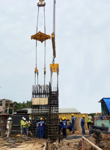
6. Install the concreting pipe.
– The concrete pouring pipes are made of steel with a diameter of 25-30cm, manufactured in sections of varying lengths of 2m, 1.5m, 1m, and 0.5m, allowing for assembly according to the depth of the borehole.
– There are currently two methods of connection: threaded connection and cable connection. Cable connection is usually faster and more convenient. The pipe connection has a rubber gasket to prevent bentonite solution from penetrating the concrete during pouring, and is greased for easy disassembly and reassembly.
– The concrete pouring pipes are installed gradually, one pipe at a time, from bottom to top. A special support system, structured like a steel ladder, is used to support the pipes. The ladder has two hinged annular halves. When these halves collapse, forming a cone that tightly encloses the pouring pipe, the larger diameter pipe opening is held in place by the two halves. Thus, the concrete pouring pipe is suspended from the casing pipe opening via this special support. The bottom of the pouring pipe is positioned 20 cm from the bottom of the borehole to prevent blockage by soil and rocks at the bottom of the borehole.
7. Treatment of sediment at the bottom of the borehole.
– In wet drilling technology, fine particles suspended in the bentonite solution settle down, forming a layer of sediment that significantly affects the load-bearing capacity of the pile tip. After installing the concrete pouring pipe, the depth of the borehole bottom is measured again. If the sediment layer is greater than 10cm, sediment treatment must be carried out.
– Compressed air flushing method: A concrete pouring pipe is used as a sediment treatment pipe. After installing the concrete pouring pipe, a flushing head is attached to the top of the pipe. The flushing head has two ports; one port is connected to a 150mm pipe to recover bentonite solution and sediment from the bottom of the borehole to the solution recovery device. The other port has a 45mm compressed air pipe, approximately 80% long (the length of the pile). When flushing begins, compressed air is blown through the 45mm pipe inside the concrete pouring pipe at a pressure of about 7 kg/cm², and this pressure is maintained continuously. The compressed air exiting the 45mm pipe escapes upwards into the pouring pipe, creating a suction pressure at the bottom of the pouring pipe that carries the bentonite solution and sediment along the concrete pouring pipe to the solution filter. The flushing process lasts 20-30 seconds, and bentonite solution must be continuously replenished during the flushing process. Next, lower a plumb line to measure the depth. If the depth of the borehole bottom is confirmed (settling to 10cm), then simply check the bentonite solution extracted from the bottom of the borehole.
Request:
= 1.04 1.2g/cm3 (density)
=20s 30s (Viscosity)
pH=9 12 (PH)
8. Pour concrete.
After finishing blowing and washing the borehole, it is necessary to pour concrete immediately because the sand will continue to settle for a long time, affecting the quality of the piles, so the work of preparing concrete, cranes and pouring hoppers must be very smooth. . Commercial concrete used to pour piles must have a slump of 18 2cm. Concrete that is too dry or too pasty can cause blockage of pipes when pouring concrete. Concrete poured piles are poured through the concrete truck hopper, when the last concrete trucks are poured, the pressure to pour concrete is no longer great, so it is more difficult to pour concrete, to have to stuff the pipe many times and easily clog the concrete pipe.
– Concrete pouring for bored piles involves pouring concrete underwater in a bentonite solution using a pipe-drawing method. Before pouring, a cork stopper (or styrofoam ball) is placed in the pipe to separate the bentonite solution from the concrete solution inside. The cork stopper will then float to the surface of the pile and be recovered.
– Pour concrete into the funnel until it's full, cut the wire holding the stopper, and the concrete pushes the stopper down and overflows into the bottom of the borehole. The first batch flows out through the stopper by raising the pipe 20cm above the bottom.
– Slowly lower the pipe until it is completely submerged in the concrete, but still ensure the speed of the concrete moving inside the pipe (This speed is usually slow to prevent the concrete from segregating, approximately 120 mm/s).
– During the concrete pouring process, the concrete pouring pipe is gradually withdrawn in sections so that it is always submerged in the concrete mortar to a minimum depth of 2 meters. This work must be closely monitored because any mistake will immediately damage the pile due to breakage, and the concrete inside the pile will not be continuous. The pile concrete pouring process must be continuous.
– The concrete delivery rate at the hopper must also be kept consistent, matching the speed of movement in the pipe. It shouldn't be too fast, causing overflow, nor too slow, which can lead to many negative consequences and disrupt the concrete flow.
– The concrete pouring time for piles should be limited to 4 hours because the first batch of concrete will rise to the top, so an additive is needed to prolong the setting time and ensure it doesn't set before the entire pile pouring process is complete. To prevent foreign objects from falling into and clogging the pouring pipe, a 100x100 steel mesh should be welded so that the concrete must pass through it before pouring.
– To complete the concrete pouring process, the final concrete elevation must be determined. The actual elevation of high-quality concrete must be calculated and determined because the top layer often contains soil and rock. The possibility of the concrete collapsing when the casing pipe is withdrawn due to the drill pipe diameter being larger than the casing pipe must be considered. If the final pile concrete is lower than the design, connecting the piles becomes difficult and costly; conversely, if it is too high, multiple pile heads must be demolished, which is also costly.
– Once the concrete pouring process is complete, the pouring pipe is withdrawn from the pile, and the pipe sections are cleaned and stored in the designated area.
9. Withdraw the wall pipe.
– In this final stage, the supports, working platforms, and reinforcing steel anchors to the casing pipe are all dismantled. The casing pipe is slowly pulled up using a crane, and must be pulled vertically to avoid shifting the pile head centerline. A vibrating device should be attached to the casing pipe to facilitate the withdrawal process and prevent bottlenecks at the pile where the casing pipe ends.
– After withdrawing the casing pipe, sand must be filled into the pit, the pit filled, bentonite collected to create a flat surface, and a temporary barrier must be erected to protect the pile. No vibrations are allowed in the area, and no other piles must be drilled for 24 hours after the completion of concrete pouring for the pile within a radius of 5 times the pile diameter (4m).
III. CHeck quality pile.
1. Causes of defects on piles.
Because bored piles are constructed in difficult conditions, although the pile construction technology is getting more and more complete, the possibility of defective piles is still quite high. A series of causes of pile damage have been synthesized and analyzed, including the following main causes:
+ Collapsing the wall during the drilling process makes the pile cross-section shrink, but just below the pile cross-section is enlarged.
+ The friction between the concrete and the support pipe is too large, the technology of pouring concrete and withdrawing the pipe is not suitable, causing the pile to be broken.
+ The borehole cleaning has not been thoroughly done, causing the drilling mud to accumulate under the pile tip, leading to a decrease in the load capacity of the pile.
+ Concrete has too low slump causing the concrete in the pile to be loose.
+ Density of reinforcement is too high so that the concrete does not leak out of the scope of the steel cage.
+ Unevenly withdrawing the support pipe causes the pile to move horizontally locally.
Research results show that the causes of damage to bored piles are quite diverse, most of the defects are caused by inappropriate construction technology. To limit these defects, it is necessary to strictly inspect all stages of pile construction.
2. Check the quality of piles during construction.
With proper construction technology and strict quality control procedures, the possibility of pile damage can be kept to a minimum. The following factors should be checked at the site:
a) Check the Bentonite solution.
The main purpose of testing Bentonite solution is to ensure that the borehole wall does not collapse during drilling as well as during concreting and to check that the bottom of the borehole is blown before concreting.
The main parameters of Bentonite solution are usually controlled as follows:
+ Sand content: < 5%
+ Density: 1.01 - 1.05
+ Viscosity: 35 sec
+ pH: 9.5 – 12
b) Check the borehole size.
After cleaning the bottom of the borehole with Bentonite solution, the following parameters of the borehole bottom should be checked:
+ Depth measurement: The bottom of the borehole is considered clean if the depth after blowing is equal to the drilling depth (determined by measuring the depth of the drill rod reached during construction or by other equipment).
+ Use some simple penetration devices to evaluate the penetration resistance of the soil at the bottom of the pit.
Measure the diameter and verticality of the borehole.
+ State of the borehole.
c) Inspect concrete before pouring.
Concrete used in the construction of bored piles usually has to check the following parameters:
+ Drop (for each dump truck): 15 cm
+ Strength after 28 days (sampling, by pop gun for concrete at the top of piles or ultrasonic): 200 kg/cm2
+ Coarse aggregate in concrete: not larger than the particle size required by technology.
+ Concrete mix level in the borehole
+ Depth of flooding of concrete pipes in concrete mix
+ Volume of concrete poured in the pile hole
The concrete to be tested for strength shall be from the mixer truck and from the pile body concrete.
d) Take notes during construction.
During the construction process, it is necessary to record the start time, end time and incidents occurring during the performance of the following jobs:
+ Put the strut.
+ Pump Bentonite solution.
+ Drill holes.
+ Blow and wash the bottom of the borehole.
+ Set the steel cage.
+ Put concrete pipe.
+ Remove the anti-tube.
+ Concrete volume for each pile.
3. Check the quality of piles after construction.
After concreting, the quality inspection of piles should be carried out to assess the quality of pile concrete at the site, detect defects and treat damaged piles.
There are several testing methods as follows:
+ Static compression method
+ Ultrasound method
+ Stress wave method: there are PIT method, PDA method.
Lethy corp

Tags search information: provide BTC . pile,supply square pile,round pile supply,larsen poles,construction kingpost shoring,foundation construction,lethycorp pile pressing, concrete pile pressing, larsen's cunt, cyes larsen, larsen eps, pressed iron piles, pressure on people's houses, bored pile drilling,